
Small Self Powered Generator
A free-energy developer working in South Africa where it is difficult to find electronic components, has very kindly shared the details of his compact self-powered generator so that you can build one if you choose to do so. Using a small inverter, the output of the prototype is 40 watts at mains voltage and frequency and the generator is a small table-top unit which is not difficult to build. The generator uses five small 12-volt 7 Amp-Hour lead-acid batteries like this:

While this sounds like a lot of batteries, bear in mind that this is a generator which has a continuous electrical output, day and night and the batteries never have to be charged – a bit like a solar panel which works at night as well as during the day. Even if you are not familiar with electronics circuit diagrams (chapter 12 can fix that for you if you want), please try to follow along as we run through the circuit diagram and explain how the generator works. This is the circuit diagram:

The battery marked “A” powers the circuit. A rotor “C”, containing five magnets is moved so that one of the magnets passes near the coils. The coils set “B” has three specially-wound coils and the magnet moving past those three coils generates a small current in coil number “1” which then flows through the resistor “R” and into the base of the transistor, causing it to switch on. The power flowing through the transistor coil “2” causes it to become a magnet and that pushes the rotor disc “C” on its way, keeping the rotor spinning. It also induces a current in the winding “3” and that current is rectified by the blue diodes and passed back to charge battery “A”, replacing the current drawn from that battery.
When the magnet in rotor “C” passes away from the coils, the transistor switches off, moving its collector voltage very quickly up to the +12 Volt line, starving coil “2” of current. Because of the way that coils are, the coil drags the collector voltage on up and it would reach 200 volts or more if it were not connected through the red diode to all five batteries which are connected in one long chain. The batteries will have a combined voltage of just over 60 volts (which is why a powerful, fast-switching, high-voltage T13009 transistor is being used. As the collector voltage passes the voltage of the battery chain the red diode starts conducting, passing the available energy in the coil into the battery chain. That current pulse passes through all five batteries, charging all of them. The higher voltage caused by so many batteries means that higher power is fed into all the batteries from coil “2”. Loosely speaking, that is the generator design.
In the prototype, the load for long-term testing was a twelve volt 150-watt inverter powering a 40-watt mains light bulb:

The basic design shown above was then modified by the addition of two additional pick-up coils:

Coils “B”, “D” and “E” are all triggered at the same time by three different magnets. The electrical energy produced in all three coils is passed to the four blue diodes to produce a DC power supply which is used to charge battery “A” which powers the circuit. That additional input to the drive battery and the addition of two more drive coils to the stator, makes the system operate securely as self-powered, maintaining the voltage of battery “A” indefinitely.
The only moving part of this system is the rotor which is 110 mm in diameter and is a 25 mm thick acrylic disc mounted on a bearing taken from an old computer hard disc drive. The arrangement looks like this:


In the pictures, the disc looks to be hollow but in actual fact it is solid, very clear plastic. The disc has been drilled at five evenly spaced points around the circumference, that is, at 72 degree intervals. The five main holes drilled in the disc are to take the magnets which are sets of nine circular ferrite magnets, each 20 mm in diameter and 3 mm thick, making each stack of magnets 27 mm long and 20 mm in diameter. The magnet stacks are positioned so that their North poles face outwards. When the magnets have been installed, the rotor is placed inside a strip of plastic pipe which prevents the magnets escaping when the disc is spun rapidly. The plastic pipe is secured to the rotor using five bolts with countersunk heads.
The gap between the rotor and the coils can be set as anything from 1 mm to 10 mm as the coils have slotted mounts as can be seen from this picture of an earlier version of the generator:

Notice the way that the coil mounts allow the distance between the coils and the rotor to be changed. The working gap between the rotor and the coils can be adjusted so that the performance can be maximised by finding the most effective gap.
The spools of the coils are 80 mm long and the ends are 72 mm in diameter. The centre shaft of each coil is made of a length of plastic pipe with a 20 mm outer diameter and an inner diameter of 16 mm. giving a wall thickness of 2 mm. After being wound, that inner diameter is filled with a series of welding rods with their welding coating removed, and which are then encased in polyester resin although a solid bar of soft iron is a good alternative:


The three strands of wire which form coils “1”, “2” and “3” are 0.7 mm diameter wire and they are twisted together to become a “Litz” wire before being wound into the coil “B”. This produces a much thicker composite wire strand which is easy to wind accurately on to the spool. The winder shown above uses a chuck to grip the coil core for winding, but any simple winder will work well.
The developer does the Litzing by stretching out three strands of wire, each coming from a separate 500 gram reel of wire. The three strands are clamped at each end with the wires touching each other at each end and with three metres between the clamps. Then, the wires are clamped in the middle and 80 turns applied to the middle. That gives 80 turns for each of the two 1.5 metre lengths held between the clamps. The twisted wire is wound on to a makeshift reel to keep it tidy as this twisting has to be repeated 46 more times as the entire contents of the reels of wire will be needed for this one composite coil:

This time the turns are applied in the opposite direction. Still the same 80 turns, but if the last length was ‘clockwise’ then this stretch of wire will be turned ‘counter-clockwise’. This alternation of direction gives a finished set of twisted wires where the direction of twist reverses every 1.5 metres along the length. That is the way that commercially produced Litz wire is made, but I seriously doubt that the resulting performance is any better than if the direction of wind was never changed and the twisted wire had the same direction of twist along its whole length.
This very nice twisted group of wires is now used to wind the coil. A hole is drilled in one spool flange, right beside the central tube and core, and the start of the wire fed through it. The wire is then bent sharply at 90 degrees and fed around the shaft of the spool to start the winding of the coil. The wire bundle is wound carefully side by side along the length of the spool shaft and there will be 51 turns in each layer and the next layer is wound directly on top of the first layer, moving back towards the start. Make sure that the turns of this second layer sit exactly on top of the turns beneath them. This is easy to do as the wire bundle is thick enough to make positioning very easy. If you prefer, a single thickness of white paper can be placed around the first layer, to make it easier to see the second layer as it is wound. There will be 18 of these layers to complete the coil, which will then weigh 1.5 kilograms and in 2016 prices in the UK, the wire in this coil will cost £45 and the winding looks like this:

This completed coil now contains three separate coils in very close proximity to each other and that arrangement is excellent when one coil is powered up, for inducing energy in the other two coils. This winding now contains coils 1,2 and 3 of the circuit diagram. There is no need to concern yourself with marking the ends of each strand of wire as a simple ohmmeter will tell you which two ends have a winding between them.
Coil 1 is used as the trigger coil which switches the transistor on at the right instant. Coil 2 is the drive coil which is powered by the transistor, and Coil 3 is the first of the output coils:

System, coils 4 and 5 are simple helical-wound coils which are wired in parallel with drive coil 2. They boost the drive and they are necessary. Coil 4 has a DC resistance of 19 ohms and coil 5 a resistance of 13 ohms. However, investigation is underway at present to determine the best coil combination for this generator and it is probable that the additional coils will be the same as the first coil, coil “B” and that all three coils are connected in the same way and the driving winding in each coil driven by the one powerful, fast transistor. The present arrangement looks like this:

The two gantries can be ignored as they were only for investigating alternative ways of triggering the transistor and they are no longer used.
At this time, coils 6 and 7 (22 ohms each) are extra output coils connected in parallel with output coil 3 which is 3 strands each with 4.2 ohm resistance. They can be air-core or have a solid iron core. Testing indicates that the air-core version works slightly better than having an iron core. These two coils are wound on 22 mm diameter spools and each has 4000 turns of 0.7 mm (AWG # 21 or swg 22) enamel or shellac insulated solid copper wire. All of the coils are wound with this size of wire.
With this coil arrangement, the prototype has run continuously for three weeks, maintaining the drive battery at 12.7 volts all the time. At the end of the three weeks, the system was stopped so that it could be altered and tested with a new configuration. In the configuration shown above, the current flowing from the driving battery into the circuit is 70 milliamps, which at 12.7 volts is an input power of 0.89 watts. The output power is either 40 watts or close to it, which is a COP of 45, not counting the fact that three additional 12V batteries are being charged at the same time. That is very impressive performance for the circuit.
Again, our thanks go to the developer for freely sharing this most important circuit which he developed and for his future modifications, the first of which is shown here:

In this arrangement, coil “B” is also pulsed by the transistor and the output from the coils around the rotor is now directed to the output inverter. The drive battery has been eliminated and a low-power 30V transformer and diode run from the inverter output replaces it. Spinning the rotor generates sufficient charge on the capacitor to get the system running without a battery. The output power has now risen to 60 watts which is a 50% improvement. The three 12-volt batteries have also been eliminated, and the circuit can run with just one battery. Continuous power output from a single battery which never needs to be recharged is a very satisfactory situation.
The next advance is a circuit arrangement using a Hall-effect sensor and an FET transistor. The Hall-effect sensor is aligned exactly with the magnets. That is, the sensor is positioned between one of the coils and the rotor magnet. There is a 1 mm clearance between the sensor and the rotor and the arrangement looks like this:

Or when the coil is in position, the view from above is like this:


This circuit has a 150 watt continuous output and it uses three 12-volt batteries. The first two batteries are used, one to power the circuit while the second one is being recharged through three diodes wired in parallel to improve the recharging current flow. The two-pole two-way changeover switch “RL1” swaps the batteries over every few minutes using the circuit shown below. This technique keeps both batteries fully charged.
The recharging current also flows through a second set of three diodes wired in parallel, recharging the third 12-volt battery which powers the inverter which supplies the load. The test load was a 100-watt bulb and a 50-watt fan.
The Hall-effect sensor drives a C5353 transistor but any fast-switching transistor such as a BC109 or a 2N2222 transistor can be used. You will notice that all of the coils are now being driven by the IRF840 FET. The relay used for the switching is a latching type such as this one:

And it is driven by a low current draw ILC555N timer like this:
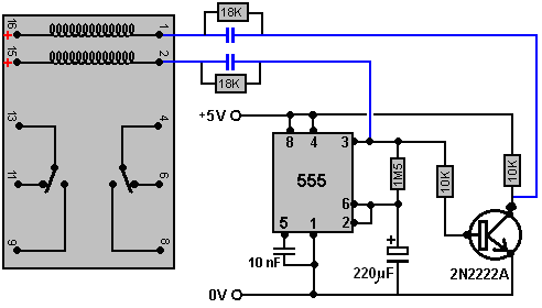
The capacitors shown in blue are chosen to operate the actual physical relay which is used in the circuit. They give the relay a brief switching pulse every five minutes or so. The 18K resistors across the capacitors are to bleed off the capacitor charge during the five minutes when the timer is in it alternative state.
However, if you wish to avoid switching between batteries, the the circuit can be arranged this way:

Here, the battery which powers the inverter which supplies the load is increased in capacity and while the developer used two of his 7 Amp-Hour batteries, you can use a standard 12-volt 12 Amp-Hour battery intended for a mobility scooter. All but one of the coils is used to supply current to the output battery and the one remaining coil, which is part of the three-strand main coil, is used to supply the drive battery directly.
The 1N5408 diode is a 100-volt 3-amp component. The diodes which are not shown with a type number against them can be any diode in the 1Nxxx range of diodes.
The coils shown connected to the IRF840 FET transistor are physically positioned around the circumference of the rotor. There are five of these coils as the grey shading indicates that the righthandmost three coils are the separate strands of the main 3-wire composite coil which was shown in the earlier circuits